 1 (866) 313-2180
 SALES@FORKLIFTTIRE.COM


Posted by Forklift Tire Company on 17th Mar 2020
A typical mobile scissor lift is more than a platform on crossed arms. A self-propelled unit combines a guarded work platform, platform and ground controls, a scissor stack, a hydraulic or electric lift actuator, a chassis, drive and brake hardware, wheels and tires, an onboard power system, emergency lowering, and safety devices such as pothole guards and tilt sensing. This guide walks through each component group and what it does.
Scope note: This guide covers mobile personnel scissor lifts, often classified as mobile elevating work platforms (MEWPs). Industrial lift tables and dock lifts can use a similar crossed-arm mechanism, but they are a separate equipment family with different configurations and standards, and the two should not be treated as interchangeable. We use a typical self-propelled slab machine as the example; exact parts, names, and control logic vary by manufacturer, model, serial range, and options.
Jump to a section:
- Labeled diagram of a typical scissor lift
- Platform and operator-area parts
- Lifting mechanism
- Chassis, mobility, and power
- Controls and safety-related systems
- How the parts work together
- What to check before ordering wheels or tires
- Safety and inspection boundary
- Frequently asked questions
- Sources
Labeled Diagram of a Typical Scissor Lift
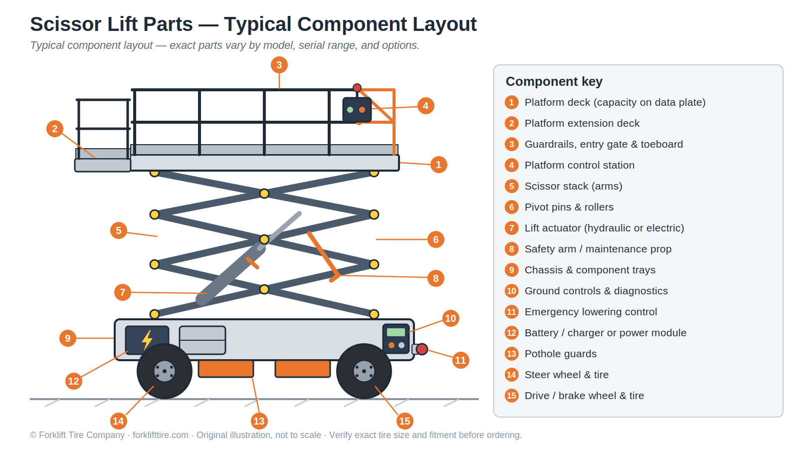
The numbered callouts above identify the components covered in this guide: platform deck and extension, guardrails and entry gate, platform controls, scissor stack, pivot pins and rollers, lift actuator, safety arm, chassis and component trays, ground controls, emergency lowering control, battery or power module, pothole guards, and the steer and drive wheel-and-tire positions.
Platform and Operator-Area Parts
Platform deck and extension
The work platform supports occupants, tools, and permitted materials within the machine's rated capacity. Many models add a roll-out extension deck to reach over obstructions; on some machines the extension carries a lower rated capacity than the main deck. Both figures come from the data plate and manual for the exact model, never from a general guide.
Guardrails, entry gate, and toeboard
The guardrail system, entry gate or chain, and toeboard form the platform's edge protection and access system. On the personnel scissor lifts OSHA describes, guardrails are part of the machine's fall-protection design rather than an optional accessory. Whether additional personal fall protection is required depends on the machine, the work context, and the employer's program — follow the exact manual and your site rules rather than a universal rule from any article.
Platform control station
The upper control station is where the operator runs the machine: typically an emergency stop, a function-enable interlock, a joystick or switches for lift and drive, steering controls, a horn, and indicator lights. Layouts differ between manufacturers and even between models in one product line, which is one reason operator familiarization on the specific machine is required.
Manual storage, decals, and the data plate
A weather-resistant manual box, the warning and instruction decals, and the serial or data plate are working parts of the machine, not decoration. The data plate carries the exact machine identity — model, serial number, rated capacity, occupant limit — that inspection, operation, and parts ordering all depend on. If decals or the plate are unreadable, the machine is not ready for service. The same identification habit applies across equipment types; see our guide to reading a forklift data plate for how much fitment information a data plate carries.
Lifting Mechanism
Scissor stack (scissor arms)
The crossed structural members that give the machine its name are the scissor stack. They guide the platform through vertical travel as their geometry changes. The arms themselves do not power the lift — they are structure, not actuator.
Pivot pins, rollers, and wear pads
The scissor stack articulates on pivot pins and rollers, with wear pads and retainers guiding and holding the moving members. These are inspection points and wear points; checking and servicing them belongs to qualified personnel following the machine's own manual.
Lift actuator and controlled lowering
The lift actuator changes the geometry of the crossed arms so the platform rises. Many machines use one or more hydraulic cylinders; some newer designs use electric actuation instead. Lowering is controlled by the machine's designed hydraulic or electric system rather than by simply "releasing pressure." The exact actuator, valves, sensors, and emergency-descent procedure are model-specific.
Safety arm (maintenance prop)
Many scissor lifts carry a fold-out safety arm that supports the raised scissor assembly during inspection or service — and only then, used exactly as the manual instructs. It is a maintenance device, not an operating stabilizer, and no one should work beneath an elevated platform without the manufacturer's approved procedure and support device in place.
Chassis, Mobility, and Power
Chassis and component trays
The lower structure of a self-propelled scissor lift is the chassis. Depending on the model it carries the wheels and tires, drive and brake hardware, batteries and charger or an engine, hydraulic or electric lift components, ground controls, the emergency-lowering control, pothole guards, and swing-out component trays for service access. Packaging varies widely between models, which is why "the base" is too vague a word for a careful parts guide.
Drive, steering, and brakes
Self-propelled machines drive and steer from the chassis, and brakes hold the machine when stopped. On a typical slab scissor lift some wheel positions are driven, some steer, and some carry brake hardware — and which positions do what is model-specific. This matters when ordering parts, because a wheel assembly for a braked position is not the same part as its non-braked counterpart.
Wheels and tires
Wheels and tires carry the machine's wheel loads and provide the designed contact and traction at the floor or ground. Depending on the model and position, a wheel assembly may also interface with steering, drive, or brake hardware. Slab machines commonly run solid non-marking tires to protect finished floors; rough-terrain models run treaded pneumatic or foam-filled tires. Inspect tires and wheels as the manufacturer's manual requires — for damage, missing material, abnormal wear, loose hardware, or an incorrect assembly — and treat replacement as a specification match: exact model, serial range, tire size and construction, wheel and hub configuration, and brake position. Our guide on how to choose scissor and boom lift tires covers sizes, compounds, and replacement considerations in depth.
Batteries, charger, or engine — and how power reaches the lift
It helps to keep three ideas separate. The energy source is commonly an onboard battery pack with a charger, or an internal-combustion engine on rough-terrain models. Power distribution is how that energy reaches the machine's functions: hydraulic, electric-plus-hydraulic, or fully electric architectures all exist in current manufacturer lineups. The lift actuator is what actually raises the platform — often a hydraulic cylinder, sometimes an electric actuator. "Electric" and "hydraulic" are not competing machine types: a battery-powered scissor lift may use electric drive motors and a hydraulic lift circuit, while newer all-electric designs eliminate hydraulics entirely.
Controls and Safety-Related Systems
Ground control station
The ground station typically provides a key selector for choosing platform or ground operation, lift and lower controls, an emergency stop, and on many machines a diagnostic display. Operating the machine from the ground with occupants on the platform is restricted to the situations the manufacturer permits, such as emergencies and specific service procedures.
Emergency stop and emergency lowering
Both control stations typically carry emergency stop buttons. Separately, machines provide an emergency or manual lowering method so ground personnel can bring the platform down when normal power or control is unavailable. Its location and procedure are model-specific and belong to pre-use familiarization — an operator's first look at the emergency-lowering control should never happen during an emergency.
Pothole protection
Many slab scissor lifts carry deployable pothole guards under the chassis. As the platform rises, the guards deploy to reduce ground clearance as part of the machine's stability design; on documented models, limit switches verify deployment, and a failed deployment triggers an alarm and inhibits drive and steer. Treat that as a representative design rather than a universal sequence — and never as permission to operate over holes, drop-offs, or debris.
Tilt, overload, and alarms
Depending on model, market, and options, a scissor lift may monitor chassis tilt, platform load, battery state, and system faults, warning the operator or restricting functions when design limits are reached. Alarms, beacons, the horn, and the diagnostic display communicate machine state. Availability and behavior vary — the machine's own manual describes what its systems do.
Outriggers and oscillating axles (if equipped)
Certain rough-terrain and specialty models add outriggers for leveling or an oscillating axle for terrain contact. These are "if equipped" items, not standard scissor-lift parts.
How the Parts Work Together
A normal lift cycle ties the components into one sequence: the operator commands a function at a control station; the control system checks its interlocks and machine conditions; the actuator changes the scissor-stack geometry and the platform moves; safety systems monitor tilt, load, and pothole-guard state while elevated; and a controlled descent returns the platform. Every part in this guide sits somewhere in that loop — structure, power, control, or monitoring — which is why a fault in any one of them takes the machine out of service until it is corrected.
What to Check Before Ordering Wheels or Tires
Scissor-lift tire and wheel replacement is a specification match, not a visual match. Before ordering, confirm:
- Manufacturer and exact model — from the data plate, not memory.
- Serial number or serial range — parts can change mid-model.
- Tire marking and construction — size, and whether the current assembly is solid, pneumatic, or foam-filled, marking or non-marking.
- Wheel and hub details — bore, bolt or lug pattern, offset, and mounting hardware.
- Position — steer, drive, brake, or non-brake; braked positions use different assemblies on many models.
- The manual or parts-list specification — the machine documentation is the final authority.
Need a scissor-lift tire or wheel assembly? Forklift Tire Company lists replacement tire-and-wheel assemblies commonly used on certain Genie, JLG, Skyjack, and Snorkel machines that use the exact listed specifications. Have the manufacturer, model, serial number, tire marking, wheel and hub details, and brake position ready. Browse scissor-lift tire and wheel assemblies or call 1 (866) 313-2180 — email sales@forklifttire.com. Verify exact tire size and fitment before ordering.
Safety and Inspection Boundary
This is a component guide, not operator or repair training. Follow the machine-specific operator manual, your employer's training and inspection program, and applicable OSHA requirements. Do not operate damaged or malfunctioning equipment, bypass interlocks, or work beneath an elevated platform without the manufacturer's approved procedure and support device. Remove suspect equipment from service and refer it to qualified personnel.
Knowing the parts supports better pre-use inspections, but it does not replace them. Manufacturers publish model-specific pre-operation inspection lists covering tires and wheels, controls, hydraulic components, the safety arm, scissor pins, pothole guards, and the entry gate. The inspection discipline is the same one that applies across material handling equipment — our forklift daily inspection checklist shows how a pre-shift routine is structured on forklifts.
Frequently Asked Questions
What are the main parts of a scissor lift?
The work platform with its guardrails and entry gate, the platform and ground control stations, the scissor stack, the lift actuator, the chassis with drive, steering, and brake hardware, the wheels and tires, the power system, emergency lowering, and model-dependent safety devices such as pothole guards and tilt or load sensing.
Is the platform the same thing as a lift table?
No. A mobile personnel scissor lift positions people and their tools; an industrial lift table or dock lift positions goods. They can share a crossed-arm mechanism, but they are separate equipment families covered by different standards.
Are all scissor lifts hydraulic?
No. Hydraulic lift cylinders are common, but current machines use hydraulic, electric-plus-hydraulic, or fully electric architectures — and a battery-powered machine may still use hydraulics for the lift function.
What do pothole guards do?
On many slab scissor lifts they deploy beneath the chassis as the platform rises, reducing ground clearance as part of the machine's stability design. On documented models, a failed deployment triggers an alarm and inhibits drive and steer. They do not make uneven ground acceptable.
What is the difference between platform controls and ground controls?
Platform controls are the operator's station for normal work — lift, drive, steer, enable, and emergency stop. Ground controls select the operating station, provide lift and lower functions, an emergency stop, and diagnostics, and support emergency and service situations the manufacturer defines.
What information identifies the correct scissor-lift tire or wheel?
Manufacturer, exact model, serial number or range, the current tire's marking and construction, wheel and hub configuration, and whether the position is steer, drive, braked, or non-braked — confirmed against the machine's manual or parts list. Verify exact tire size and fitment before ordering.
Can a parts guide replace the operator's manual?
No. This guide explains what the components are. Operating limits, inspection procedures, emergency procedures, and exact specifications come from the manual for your machine's model and serial number.
Sources
- OSHA, Scaffolding eTool — Scissor Lifts. osha.gov/etools/scaffolding/scissor-lifts (accessed 2026-08-09).
- OSHA, Hazard Alert HA-3842 — Working Safely with Scissor Lifts (2016). osha.gov (PDF) (accessed 2026-08-09).
- Genie, GS-30/GS-32/GS-46/GS-47 Operator's Manual, Part No. 1278042GT, 10th Ed. — component legend pp. 20–22; controls pp. 23–26; pre-operation inspection p. 28; pothole guards p. 34. manuals.genielift.com (PDF) (accessed 2026-08-09).
- JLG, 1532R/1932R Operation and Safety Manual No. 3121744 Rev. I, Section 3 — ground controls, manual descent, platform controls, indicators. csapps.jlg.com (PDF) (accessed 2026-08-09).
- JLG, Understanding JLG Scissor Lift Technology — hydraulic, electric-plus-hydraulic, and all-electric architectures; pothole protection. jlg.com (accessed 2026-08-09).
- ANSI/SAIA A92.20-2021 (MEWP design) and ANSI MH29.1-2020 (industrial scissors lifts) — published catalog scopes: A92.20-2021 and MH29.1-2020 at webstore.ansi.org (accessed 2026-08-09).